

Sign In Join Free


1 / 5
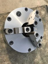
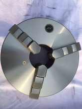
10 inch 3jaws Self Centring Chuck
| Model No. : | K11250 |
|---|---|
| Brand Name : | HERF |
| Chuck Body Material : | Nodular Cast Iron(QT) |
Zhongwei, Ningxia, China
- Manufacturer
- Trade Company
- OEM service
- Platform Certification

- SGS Certification


Product description
I. Summary
K11 250 is K11 series three jaw self-centering chuck. Chuck adopt short cylindrical center mounting.Chuck adapt plane threaded structure through the gear,scroll to make jaws move at same time for achieving self-centering of the workpiece..The steel chucks have high speed, high clamping force , long using life stc.
II. Model instruction
1. Model K11 250 : Size 250mm(10inch),
2.Chucks matched with one piece jaw
3.Short cylindrical center mounting
2. k11 250 chucks are provided with one-piece jaws(which include a set of intema jaws and a set of extemal ones)
III.Chuck Selection
1. Users should choose a suitable chuck to the demanded dimensions of workpieces and permissible clamping range of chuck
FIG 1.

TABLE 1.

2.When chose a chuck you should consider the main parameters of machine tool such as its max. speed etc .
IV. The basic parameters of cylindrical cnetre mount chucks ,See FIG. 2, TABLE. 2 AND MAIN FEATURE ,SEE TABLE 3.
FIG. 2

TABLE.2
| size | D1 | D2 | D3 | H | h | z-d |
| 250 | 206 | 226 | 80 | 80 | 5 | 3-M12 |
TABLE. 3
| SIZE | Max. input torque Nm | Max.clamping force kN | Max.speed r/min |
| Material |
|
k11 k11(QT) K11(G) | K11 K11(QT) K11(G) |
| 250 | 320 | 37 46 46 | 1600 2000 2400 |
V. Mounting a cylindrical centre chuck
1.The cylindrical centre mounting chucks connected with the machine tool spindle nose through the adaptor plate
VI. Operation.
1.Check and test items as below before operation
(1)Ensure the chuck mounting be tight.
(2)Insert the wrench into the threaded bar hole and turn it to make the Jaw move freely.
(3)Setting lowest spindle rotated speed if it runs normally then increase speed and check its run-out and other abnormal phenomenas
2. Operation of the chucks
(1)Make the workpiece to conform with the clamping arc in the
(2)Use the attached wrench to clamp workpiece( clamping individually with 4 jaws) and the input torque should not exceed the values of table 3
3.Caution
a)Do not add the tube on the wrench when clamp workpiece to avoid the input torque to exceed its limit and break chuck
b)Do not clamp workpiece in the max clamping range if possible
c) Do not run at max speed when approach the max clamping limit
d) Do not exceed chucks max speed during operation
VII. Maintenance
1. Chucks should be maintained while the machine tools maintain
2. Lubricate and clean (use the compressed air) the chucks every day in order to maintain its accuracy and durability
3. Wash and lubricate all the working surface of the chucks at least two times every year. When the using frequency of the machine tool grow or at the special operation conditions, add the maintenance times of the chucks
Zhongwei, Ningxia, China
- Manufacturer
- Trade Company
- OEM service
- Platform Certification
- SGS Certification
Send your inquiry to this supplier
Product Alert
Subscribe to your interested keywords. We will send freely the latest and hottest products to your Inbox. Don't miss any trade information.
Your use of this website constitutes acknowledgement and acceptance of our Terms & Conditions.
Copyright © 2009-2024 Bossgoo Co., Ltd. All rights reserved.
